OPLOT,points(0,*),points(1,*),psym=-1
OPLOT,points(0,*),-points(1,*),psym=-1
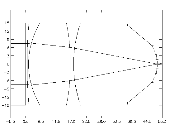 Figure 1 - EXAMPLE Lens System with Focal Trajectory
The files necessary to follow this example in PV-WAVE are in the EXAMPLE directory which is installed on the system along with ALSSP. See the Installation Instructions for information on how to copy the EXAMPLE directory to your own directory tree. Before running any of the commands in this example, make sure that you are in the EXAMPLE directory.
The first step in setting up a lens system is to build the system parameter file. In this case, the system was designed using BEAM THREE, so the OPTICS file is available. That data is saved in the file 'example.opt':
6 surfaces w25r4c6.opt
Index    Zvx F  Dia    Curv   Shape  Cx  Mir/Lens
--------:----------:-:------:---------:-----------:-------:-------------:
1       : 0.5      :S: 30   :         :           :       : iris        :
1       : 1        :S: 30   : 0.0049  : 124.1379  : 0     : lens        :
0.5613  : 1.5      :S: 30   : 0.0372  : -0.3251   : 0     : lens        :
1       : 16.62    :S: 30   : -0.0107 : 18.1977   : 0     : lens        :
0.5613  : 17.827   :S: 30   : 0.0230  : -0.9181   : 0     : lens        :
1       : 53.4944  :S: 40   : -0.0169 : 1.2129    : 0     : film        :
0.5613 : Syntactic Foam : 0.6983 : 2613.5 : -1.25 : 1.0 : 0.0
GENERATE_SYSTEM will convert this file to a form that CALC_LENS can use. However, BEAM THREE only does ray tracing, so does not provide information about the system frequency or the ambient conditions. Some of this information is specified in the BEAM THREE OPT file by the BEAM THREE user. BEAM THREE reads the number of surfaces from the first line of the OPT file, then only reads that number of data lines. Lines after that can have anything on them, including additional information on the lens materials which BEAM THREE does not use. GENERATE_SYSTEM requires an extra line for each lens material (except water). These lines contain the refractive index (matching that in the body of the OPT file), the material name, the material density, the coefficients for the speed of sound in the material, and the coefficients for the attenuation rate of sound in the material. The items must be separated by colons or commas. The sound speed coefficients are specified as the constants A and B in the equation Speed=A+B*T, with A in m/sec and B in m/sec/ degrees C. A constant sound speed can be entered by setting B to zero. The attenuation coefficients are specified similarly, as the constants A and B in the equation Attenuation=A+B*f, with the units dB/cm and db/cm/kHz, respectively. Again, a constant attenuation can be specified by setting B to zero.
This information will be stored in a system header file 'system_header':
/logfile                ; Use log file 'batch.log'
/nopressure             ; Do not do pressure calculation, only ray trace.
/trace2d                ; Do ray trace in xy plane only.
/summation              ; Do ray trace for summation method.
/savefile               ; Save results in filename.save
Sal=0                   ; Water Salinity, parts per thousand
Depth=1.0               ; Water Depth, meters
freq=900k               ; Frequency, Hz
xrange=[0,65]           ; X range to display
yrange=[-25,25]         ; Y range to display
num_rays=301            ; Number of rays to trace
waterdensity=1.0        ; Water Density, g/cm^3
wateratten=0.0          ; Water Attenuation, dB/cm
In order to decide where elements should be placed, the focal point of the system for various source angles must be found. GENERATE_SYSTEM will make parameter files to do this automatically if given the desired source angles. In this case, source angles of 0 degrees, 1 degree, 2.5 degrees, 5 degrees, 10 degrees, and 25 degrees will provide a good picture of the retina shape. In addition, the point source distance must be defined. For this lens system, the targets will be approximately 25 meters from the lens, so this will be used as the point source distance. The lens material used in this design is syntactic foam, which has a sound attenuation rate of approximately 1.0 dB/cm at 900 kHz. From within PV-WAVE, the command to make the desired parameter files is:
GENERATE_SYSTEM ,'example.opt',sys_header='template/system_header' ,angles=[0,1,5,10,25],Temperature=10.0,dist=2500,/mouse,/verbose
In the process of generating the parameter files, GENERATE_SYSTEM will ask the user to select the regions of the ray-trace plots in which to search for focal points. See the MOUSEBOX instructions for more information. GENERATE_SYSTEM also provides a batch file which contains the commands required to run the generated parameter files, so that should be run next. It will take approximately 20 minutes to run. The PV-WAVE command to run a batch file is the "@" symbol followed by the batch file name. The batch file generated by GENERATE_SYSTEM is named "batch", so the command to run it is:
@batch
After running the batch file, the results of the focal point determination routines are held in the log file 'batch.logm'. In order to view those results, the program GET_LOG can be run and the results printed and plotted. The output of GET_LOG is described in its description under Utility Programs.
points=GET_LOG('batch.logm')
print,points
CALC_LENS
,'t0_10',/view,num_rays=5,xrange=[-5,50],/square
OPLOT,points(0,*),points(1,*),psym=-1
OPLOT,points(0,*),-points(1,*),psym=-1
Figure 1 - EXAMPLE Lens System with Focal Trajectory
Figure 2 shows the resulting plot. The lens system is the five curved surfaces on the left and the retina is the plus symbols connected by line segments. The left-most lens element is a planar surface which doesn't affect the rays except to define the aperture of the system. In BEAM THREE, this is an iris. The next two surfaces represent the first syntactic foam lens. The first is an oblate ellipsoid, the second a hyperboloid. The final two surfaces are a second syntactic foam lens. The front surface is another hyperboloid and the back surface is a prolate ellipsoid. The focal points found for each source angle are shown as plus symbols ('+') in the figure, and are joined by line segments to approximate the ideal retina shape for the lens system. Note that this system is symmetric about the x-axis, so the focal points found for positive source angles can be mirrored for the corresponding negative source angles. Although it appears that only three rays were traced instead of the five specified in the CALC_LENS command, all five are shown on the left-most side of the plot. The outer two are clipped by the first lens surface, due to round-off error.
The next step in analyzing this system is to compute beam patterns. The program MAKE_BEAMS2 will be used to generate the parameter files to do this. Since the retina for this system is not an arc, the element must be moved along a trajectory approximating the retina shape. However, the retina can be approximated as a collection of arcs for small changes in the source angle. The center of each arc is referred to as the secondary principal point in optical lens design. The program FOCI_CIRC1 finds the parameters of these arcs, which can then be fed to MAKE_BEAMS2. See the instructions for GET_LOG and FOCI_CIRC1 for more details on the output of these programs. In brief, foci(5:7,n) is the x,y,z coordinates of the secondary principal point of the nth source angle and foci(8,n) is the radius of the corresponding arc which passes through the focal point.
The first line of the next set of commands removes the batch file from the previous set of instructions so we don't run them again ( MAKE_BEAMS2 appends to the end of the file rather than removing it.) If the second and third lines have already been executed in the current PV-WAVE section, the arrays "points" and "foci" will already be defined, and so the lines need not be executed again. They are include here, however, to ensure that "points" and "foci" contain the correct information.
$rm batch
points=GET_LOG('batch.logm')
foci=FOCI_CIRC1(points)
MAKE_BEAMS2
,foci(5:7,0),foci(8,0),[0,1],'t0_10',numpos=51
MAKE_BEAMS2
,foci(5:7,2),foci(8,2),[4,6],'t5_10'
MAKE_BEAMS2
,foci(5:7,3),foci(8,3),[9,11],'t10_10'
MAKE_BEAMS2
,foci(5:7,4),foci(8,4),[23,27],'t25_10'
@batch
This will generate four data sets. Note that the default of 101 positions was used on all but the first MAKE_BEAMS2 call. The first call is generating half the arc length (1 degree instead of 2) and so half as many points are used to give identical spacing. Since the source is on the x-axis for this example, the response will be symmetric and the results can be mirrored, halving the number of computations required. Alternatively, the first MAKE_BEAMS2 line could have specified an arc range of [-1,1] and used the default 101 positions. MAKE_BEAMS2 generates parameter files named by using the system file name plus "a1" appended to the end. These can be plotted using KPLOT:
KPLOT ,'t0_10a1',/find3db,/mirror,xticks=8,yticki=6,/two_way ,origin=foci(5:7,0),title='EXAMPLE: On-axis Source, Point Element',/side
KPLOT ,'t5_10a1',/find3db,xticks=8,yticki=6,/two_way,origin=foci(5:7,2) ,title='EXAMPLE: 5 degree off-axis Source, Point Element',/side
KPLOT ,'t10_10a1',/find3db,xticks=8,yticki=6,/two_way,origin=foci(5:7,3) ,title='EXAMPLE: 10 degree off-axis Source, Point Element',/side
KPLOT ,'t25_10a1',/find3db,xticks=8,yticki=6,/two_way,origin=foci(5:7,4) ,title='EXAMPLE: 25 degree off-axis Source, Point Element',/side
The results of the first and last KPLOT commands are shown in Figures 3 and 4. Note that the keyword parameter /two_way was specified in each command so that the two-way rather than one-way beam patterns are shown. Also, the keyword /mirror was specified for the first command so that the response, which was calculated from 0 to 1 degrees, would be mirrored to get a plot from -1 to 1 degrees.
The numerical results are tabulated in Table 1. Note that the /find3db option in KPLOT normalized all the plots so that the peak amplitude was 0 dB. Adding the /verbose keyword to the KPLOT command will display the maximum absolute magnitude on each plot. In order to compare two beam patterns, /offset can be set to the same value for each plot. See the end of this section for an example (Pages 14 and 15).
 Figure 2 - Beam Pattern for Point Element and On-Axis Source
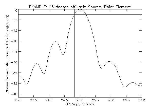 Figure 3 - Beam Pattern for Point
Element and 25 degrees Off-Axis Source
Figure 3 - Beam Pattern for Point
Element and 25 degrees Off-Axis Source
           Table 1 - Point Element Data

Source Location   Two-way beam width      Sidelobe Level
0 degrees         0.223 degrees           -36.8 dB
5 degrees         0.224 degrees           -34.8 dB
10 degrees        0.232 degrees           -32.6 dB
25 degrees        0.377 degrees           -18.4 dB
Table 1 shows the beam widths are all within the specifications, but the
sidelobe levels are all too high. However, these calculations were made for
a point element. Any real element will have a physical size and shape which
will affect the beam widths and sidelobe levels. By adding the effect of
element size and shape into the calculations, the sidelobe levels can be
decreased for a small penalty in beam width. For example, adding a 0.268 cm
element is done by modifying the above instructions to:
$rm batch
points=GET_LOG('batch.logm')
foci=FOCI_CIRC1(points)
MAKE_BEAMS2 ,foci(5:7,0),foci(8,0),[0,1],'t0_10',numpos=51,elementfile='template/rect0.268',start=2
MAKE_BEAMS2 ,foci(5:7,2),foci(8,2),[4,6],'t5_10',elementfile='template/rect0.268',start=2
MAKE_BEAMS2 ,foci(5:7,3),foci(8,3),[9,11],'t10_10',elementfile='template/rect0.268',start=2
MAKE_BEAMS2 ,foci(5:7,4),foci(8,4),[23,27],'t25_10',elementfile='template/rect0.268',start=2
@batch
This is identical to before, but an element template file has been specified
which contains the information needed for a 0.268 cm line element:
rect              ; Use a rectangular element.
0.268,0           ; Element is 0.268 cm high (y direction) and 0 cm wide (x)
direction         ; Element will always face in the same direction.
-1.0,0,0          ; That direction is (-1,0,0), which is the -x direction.
10                ; Number of points on element
In addition, the keyword parameter /start has been set to 2, which means the output files will end with a '2' so that they won't overwrite the previous output files, which ended with the default '1'. Plotting these files is done by the commands:
KPLOT
,'t0_10a2',/find3db,/mirror,xticks=8,yticki=6,/two_way
,origin=foci(5:7,0),title='EXAMPLE: On-axis Source, 0.268 cm Element',/side
KPLOT
,'t5_10a2',/find3db,xticks=8,yticki=6,/two_way,origin=foci(5:7,2)
,title='EXAMPLE: 5 degree off-axis Source, 0.268 cm Element',/side
KPLOT
,'t10_10a2',/find3db,xticks=8,yticki=6,/two_way,origin=foci(5:7,3)
,title='EXAMPLE: 10 degree off-axis Source, 0.268 cm Element',/side
KPLOT
,'t25_10a2',/find3db,xticks=8,yticki=6,/two_way,origin=foci(5:7,4)
,title='EXAMPLE: 25 degree off-axis Source, 0.268 cm Element',/side
These patterns are similar, but exhibit slightly larger beam widths and lower sidelobe levels, as expected. The results are tabulated below:
           EXAMPLE: 0.268 cm Element Data
Source Location   Two-way beam width      Sidelobe Level
0 degrees         0.246 degrees           -47.8 dB
5 degrees         0.248 degrees           -46.8 dB
10 degrees        0.255 degrees           -44.6 dB
25 degrees        0.401 degrees           -22.6 dB
Now the specifications have been met. For the 10 degrees field of view, the
beam widths are under 0.25 degrees and the sidelobe levels are below -40 dB.
For the 50 degrees field of view, the beam widths are under 0.5 degrees and
the sidelobe levels are below -20 dB.In order to visually inspect the effects of including element size, two beam patterns can be plotted on the same graph. This requires using the /noerase option on KPLOT. In addition, if the graph is to show relative amplitudes, /offset must be set to the same value for each plot. The following lines will create the plot shown in Figure 5. The offset of -35.3147*2.0 comes from the maximum absolute value (in dB) returned by the first KPLOT command (due to the /verbose option.) doubled since the plot shows two-way beam patterns (due to the /two_way option.)
points=GET_LOG('batch.logm')
foci=FOCI_CIRC1(points)
origin=foci(5:7,0)
KPLOT,'t0_10a1',/db,/two_way,/mirror,origin=origin $
 ,xticki=0.25,xminor=2,yrange=[-70,0],yticki=6,yminor=2 $
 ,title='On-Axis Source, 2-Way Beam Pattern' $
 ,/verbose,offset=-35.3147*2.0
KPLOT,'t0_10a2',/db,/mirror,/two_way,origin=origin,/verbose,psym=-1 $
 ,offset=-35.3147*2.0,/noerase
KLEGEND,['Point Element','0.268 cm Square Element'],[0,-1] $
 ,ystart=-1,xstart=-0.95
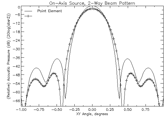 Figure 4 - Comparison of Beam Patterns
with and without Element
Figure 4 - Comparison of Beam Patterns
with and without ElementAlthough the above information and plots are useful, we might want to create a more visually compelling display of the lens's operation. CALC_LENS can generate pressure fields within a plane or rectangular volume, and KPLOT can display them as contour plots or images. The utility program MAKE_VOLUME creates a parameter file which will instruct CALC_LENS to calculate the pressure field in a plane. The first parameter is the file name of the ray- trace parameter file for the system. This is used to draw a ray-trace plot so that the user can then select the region of image space within which to calculate the pressure field. The second parameter is the name of the parameter file which MAKE_VOLUME will create. The parameters xpts and ypts specify the number of points in each dimension to sample the pressure field at. The keyword parameter /dec specifies the number of decimal points to round the pressure field's boundary coordinates to.
After the parameter file has been created, we use CALC_LENS to calculate the pressure field and KPLOT to display it. In this case, we will display an image with a 3 dB contour plot overlayed on top of it (Figure 6). The PV- WAVE commands are:
MAKE_VOLUME,'t0_10','t0_10v',xpts=60,ypts=40,dec=0
CALC_LENS,'t0_10v'
KPLOT,'t0_10v',/db,/contour,nlevels=1     ; Create correct axes for image.
KPLOT,'t0_10v',/db,contour=3              ; Display image.
KPLOT,'t0_10v',/db,/contour,/noerase      ; Overlay contour plot.
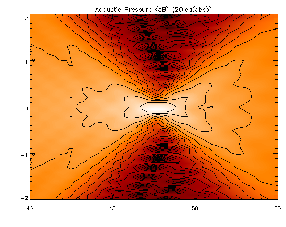 Figure 5 - Pressure Field for On-Axis Point Source
![]() Go back to the Overview of ALSSP
Go back to the Overview of ALSSP
![]() Go to the CALC_LENS Description
Go to the CALC_LENS Description
kevin@fink.com