
However, geometrical acoustics breaks down in certain circumstances. At the focal point of a lens system, where many rays cross, geometrical acoustics predicts infinite sound pressures. On the other hand, it predicts zero pressure levels outside of the region of the lens system that contains rays. In reality, the pressure levels follow a somewhat smooth continuum, large but finite at the focal point, and small but non- zero outside the ray-containing region of the lens system.
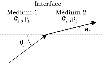
In the ray tracing portion of the simulation, the initial magnitude of each ray is set to 1. Snell's Law is used to calculate the path of each ray as it passes through each interface:

The software also takes into account the sound attenuation due to each material and the transmission coefficient at each interface. In each section of the lens the sound attenuation, in dB/cm, is multiplied by the calculated physical path length to find the attenuation. The total attenuation for each ray is the sum of the attenuation in each section of the lens.
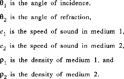
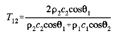
The transmission coefficient depends on the angle of incidence at each interface and the densities and sound speeds of the materials at each interface. The equation is the solution of the wave equation for a parallel wavefront impacting a flat surface, thus it assumes that the curvature of each interface is small compared to the wavelength of sound. In terms of the parameters described in Figure 3, the transmission coefficient from one material to the next is

The phase of each ray is the total acoustic path length of the route that it
follows through the lens system minus the shortest acoustic path length for any ray.
Thus all the ray phases are greater than or equal to zero, with zero phase
corresponding to the shortest acoustic path length. The acoustic path length in each
lens section is
 , where f is the frequency of the sound, l is the physical path
length in the material, and c is the speed of sound in the material.
Once a ray trace has been made, an approximation of the pressure field along a given line can be found by calculating the density of rays crossing the line as a function of position along the line. In addition, the focal point can be approximated by finding the point in space that has the highest density of rays. As discussed before, however, this method predicts infinite intensity at the focal point and zero intensity outside of the ray-containing region of image space.
In order to determine whether or not an acoustic lens design will meet the design requirements, it is necessary to characterize it with more detail than geometrical acoustics permits. Two measurements of the beam pattern of a lens system that are particularly important are the beam width and the sidelobe heights. Geometrical acoustics predicts nothing about these parameters, but they can be found using wave theory.
Return to Title Page and Table of Contents
kevin@fink.com